Hardware
- Frame
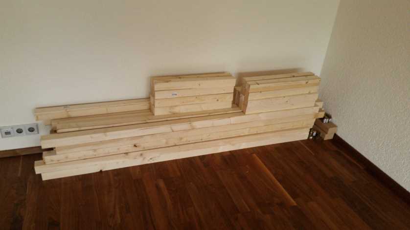
- 26 x 2m 5,8x5,8cm wooden beams
- 20 x 1m 5,8x5,8cm wooden beams
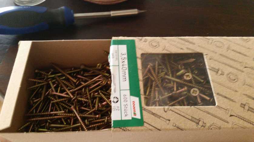
- 1200 x 3,5x40mm screws
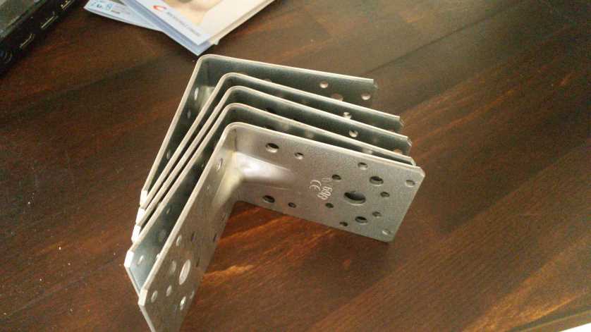
- 96 x 50x50x10mm angel connectors
- 20 x 90x90x65mm angel connectors
- 200 x cable ties, 40cm
- 15 x hot glue sticks, 7mm
- Electronics
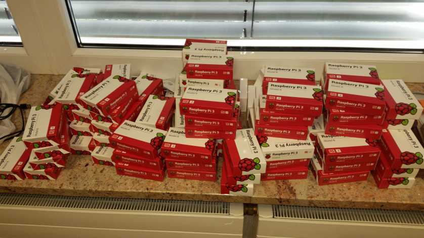
- 97 x Raspberry Pi 3 Model B
- 96 x Raspberry Pi Cams V1
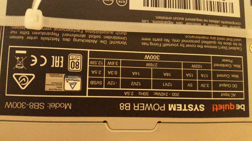
- 10 x be quiet! System Power 8 300 Watt, BN256
- 16 x LED Strip 5 m 5050, 300 LED, outdoor cw, EEK A++ -
- 300m CAT 5 cable
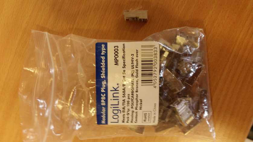
- 250 x LAN connectors
- 100 x micro USB connectors
- 50 x Trans MOSFET N-CH, 30V, 62A, TO-220AB
- 50 x Resistor 1/4W, 5%, 10 K-Ohm
- 50 x Resistor 1/4W, 5%, 10 Ohm
- 12 x Solderable screw clamp 3-pol, RM 5,08 mm, 90°
- 50 x screw clamp 2-pol, RM 5,08 mm
- 12 x Punch raster board, hard paper, 50x100mm
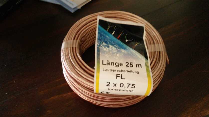
- 2 x 25 m speaker cable, 2 x 0,75
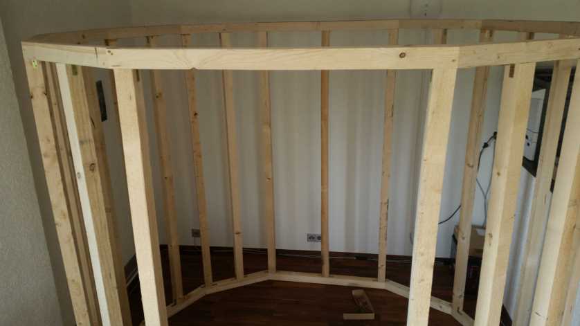
Frame
Construction
We have used the free Version of
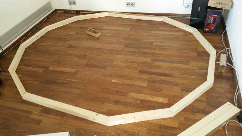
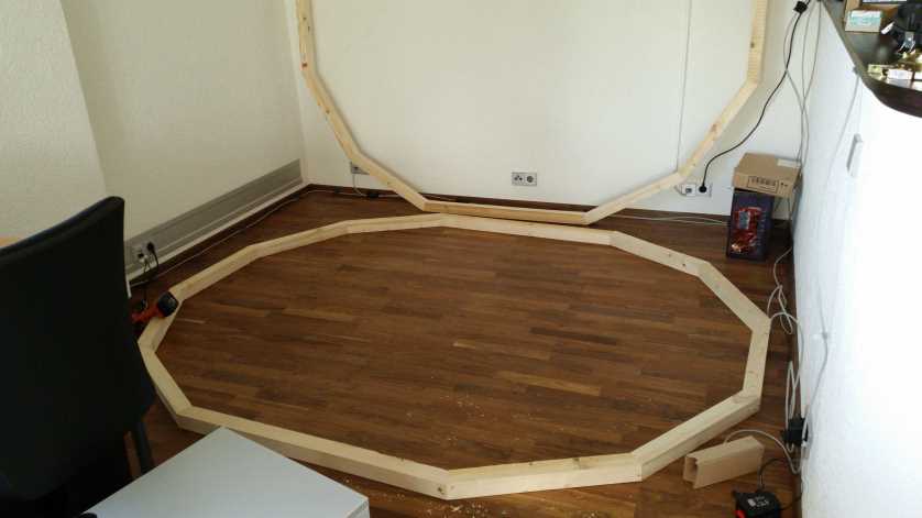
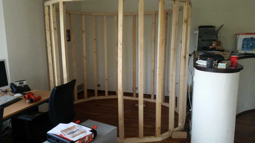
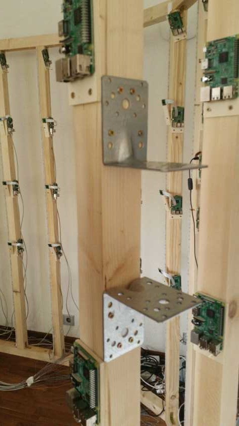
Sketchup for constructing our frame. The frame is build as a dodecagon and there are 24 vertical timbers. So we were able to attach 96 Raspberry Pis with cam (4 on each timber).
We used 5.8 x 5.8 cm thick wooden beams as these were very cheap and fit the size to the Rapsberry Pis.The upper and lower frames were bolted with 3.5 x 40 mm screws and the vertical beams were fixed with angel brackets.
 Possible improvements
Building the Frame of wood is quite cheap, but not the easiest way. It could also be built with aluminum profiles and so you could save the work of sawing and screwing
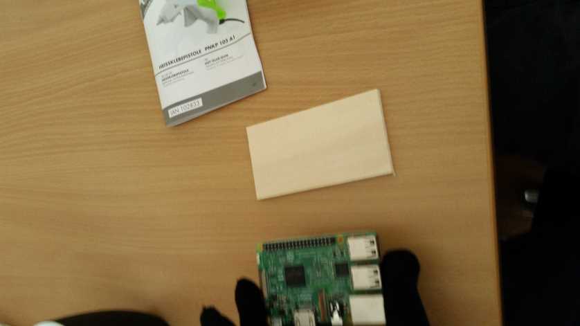
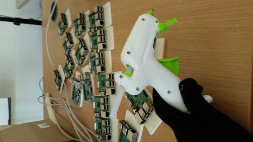
Hardware setup
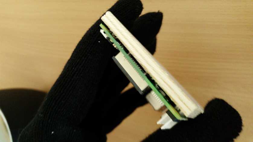
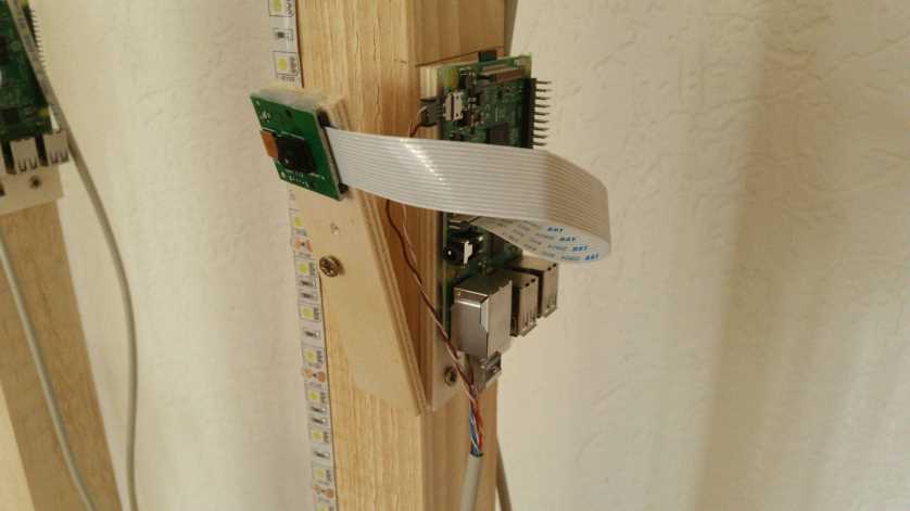
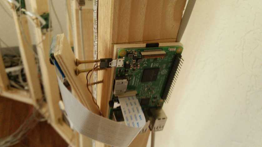
We have glued all Raspberry Pis with hot glue to small wooden boards. So we did not have to handle with small screws and could fix the pis on the boards with the same screws we took for the frame.
In this case you only have to adjust to that the opening for the SD card is still reachable.
 Cable
Cable
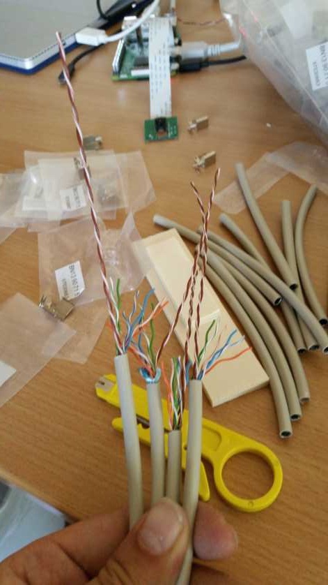
For the cables we used Cat 5 LAN cables, of which we used 6 lines for the data transmission and two cables for the power supply of the Raspberry Pis.
In this case, we have found that the cables for the power supply must be less than 80 cm, since there would be problems with the power supply. That is why we have pulled out the two cables and fitted them perfectly for the connection between power supply and Raspberry Pi.
Possible improvements
You should use cable with a higher cable diameter than LAN cables so that the power supply can be ensured.
 Fixing the power supplies
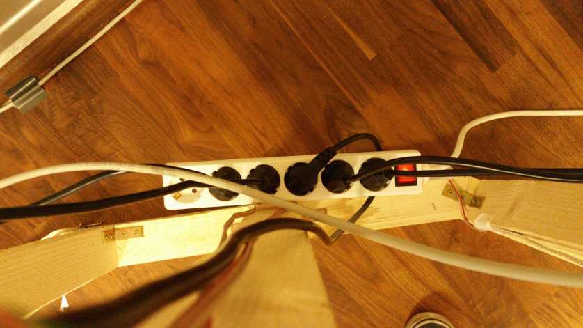
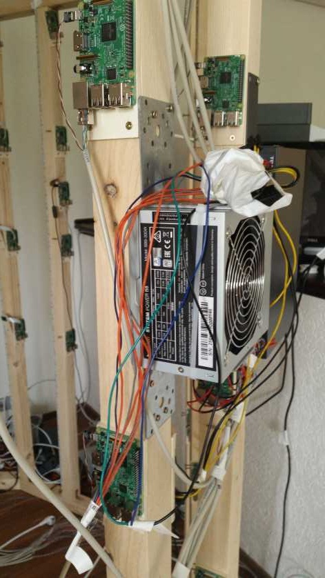
We have fixed the power supply units with angle connectors to the rack and fixed them with cable ties.
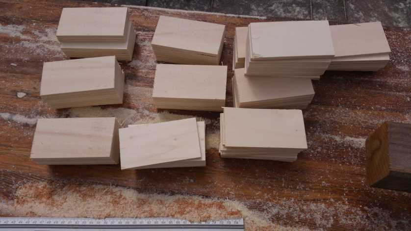
 Camera fixture and viewing angle adjustment
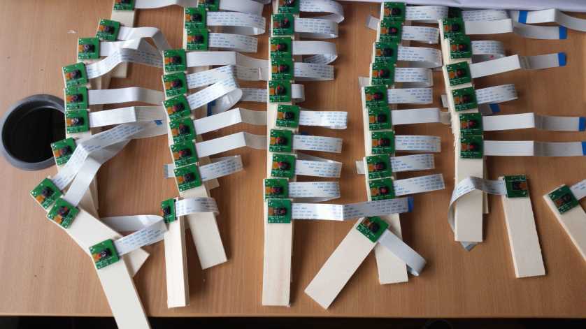
Each picam module is glued onto a small wooden plate (roughly 2.5cm x 10.5cm), which in turn is attached to the pillars of the scanner cage via three wood screws (3.5mm x 40mm) that are used to adjust the camera’s viewing direction.
The bottom screws are used to tightly fixate the position of the plate by pressing it onto the two screws at the top. The top two screws are used to adjust the viewing angle. By screwing either the left or right screw one further in, the camera’s horizontal viewing angle is shifted to the left or right. By screwing both further in or out by the same amount, the camera’s vertical viewing angle is shifted. The vertical angle can also be adjusted by moving the base of the camera’s wooden plate further up or down the pillar.
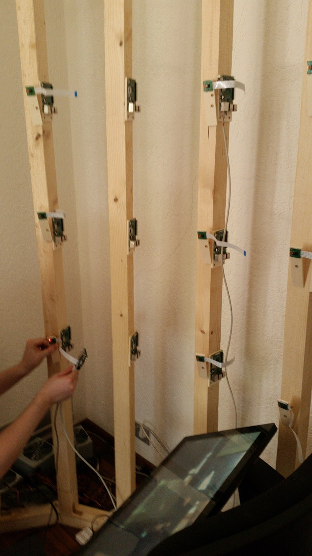
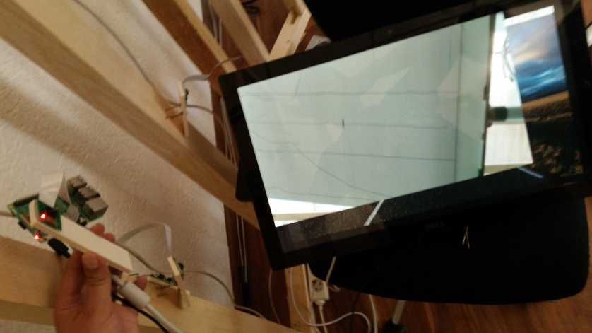
We set up each camera this way by actually configuring a sort of “mobile pi” that we could move around with us inside the cage. The PI was powered via a lengthy cord connected to a USB power hub, and connected to a local monitor in the middle of the body digitizer that was used to stream video from the camera. We would move from camera to camera, connecting it to the mobile pi and adjusting angles until whatever the video stream showed seemed right. The process required two people, one for holding the mobile pi and keeping the wooden camera plate in place until it was screwed tight, and the other one for doing the actual screwing.
The actual final viewing direction was mostly “eye-balled”, mostly to speed up the process of finishing work on 100 of these cameras. The only thing we aimed for was to roughly maximize the area overlap of the things two adjacent cameras (in horizonal and vertical directions) could see so the algorithms had an easier time finding overlapping feature points.
 Possible improvements
Setting up the camera via pre-configured camera pan or tilt mounts would have been easier, but with roughly 100 cameras in our setup, costs would quickly rack up if we had to purchase one mount for each of the cameras. The wooden plates however can be picked up by the square meter in most commodity hardware stores and cheaply sawn into small plates of your desired size.
The adjustment process could be done by a single person if you finish attachment of all the PIs, and the power setup, before you deal with camera positioning. This was not the case for us because we were still figuring out how to handle the power supply when we attached all the cameras.
Currently, we haven’t investigated whether more detailed camera viewing angle adjustment might result in a higher quality 3D scan. From the surface it sounds reasonable, because at the very least we would most likely be able to achieve a higher area overlap if we spent more time on the process.
Electronics
Power supply
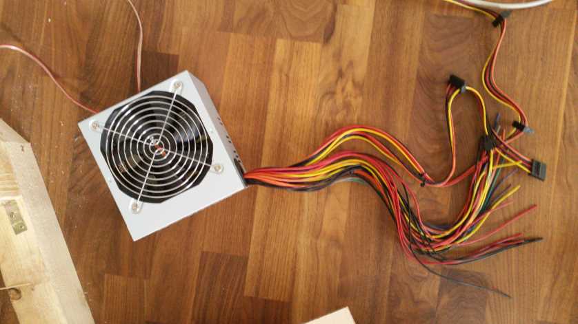
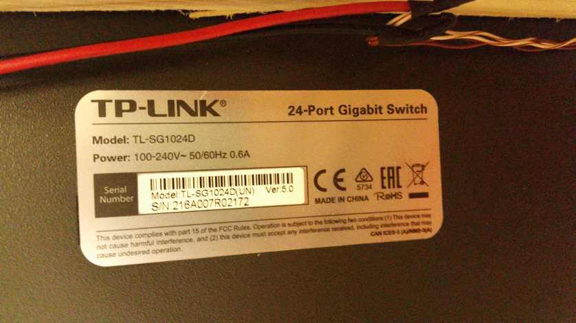
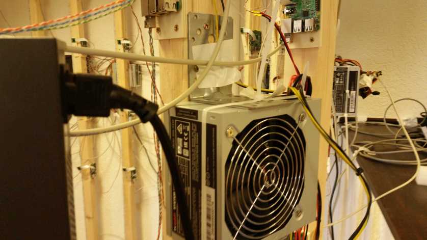
300W consumer PC power supplies are used to provide power for both LED strips and all Raspberry PIs. Network switches and projectors are powered directly via standard AC wall power outlets.
PC Power Supply
PC Power supplies provide power at voltages of 3.3V, 5V and 12V. 5V is used for the micro-USB connectors that provide PI power supply, and 12V is used for the LEDs. 3.3V is left unused. The maximum amount of power you can draw from them will generally be printed on the side of the power supply.
In total we use 10 power supplies to power 100 Raspberry PIs and 40 LED strips. We connect 10 PIs and 4 LED strips to one power supply unit each.
We source the power from the ATX power wires that are usually used to power mainboards in consumer PCs. After cutting away the ATX connector, the exposed color-coded wires can be used directly to supply electricity to whatever is connected to them. ATX wire color coding is standardized and can be found on Wikipedia for example.
The green "Power ON" and one of the black ground cables have to be connected for the power supply to turn ON. This is achieved by twisting the exposed wire together and using insulating tape to both electrically insulate it as well as keep it in place. At this point turning the power supply on and off is done via the main power switch on the back of the power supply.
Raspberry PI power supply
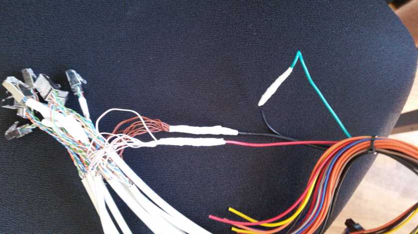
For the micro-USB / PI power supply, we used one of the five red 5V power supply lines (and accompanying black ground lines) for two PIs each. The actual connection was made by soldering the ends of the 5V wires and ground wires together with the respective wires from the ethernet cable. After soldering the wires were insulated with insulating tube to prevent short circuits in case they touched something else.
Problems and possible improvements
Initially we a single 12V wire to all four LED strips connected to a power single power supply unit. For unknown reasons this caused the smaller wires connected to the LED strips themselves to quickly heat up. We chose not to continue that experiment for lack of electrical engineering knowledge and instead tried using the the two available yellow 12V wires to power two LED strips each instead, which solved the problem of the wires running hot.
We noticed that the voltage available at the 5V outputs dropped significantly when no power was drawn from the 12V sources, and actually seemed to increase in proportion to the amount of power drawn at 12V. Early on this caused issues because PIs were underpowered until we connected LED strips to each of the power supplies. We have not figured out why this happens at all. It might be a quirk with PC power supplies or something else fundamentally flawed with our setup.
It should also be noted that the two thin, separated ethernet wires we used to power PIs caused voltage drop offs that convinced us to minimize the lengths of the ethernet cables in order to minimize the voltage drop offs wherever possible.
We turn power supplies on and off by using the actual power supply switches, but as an upgrade they could also be controlled remotely by controlling the connection between the green "POWER ON" wires and the black ground wires via another raspberry PI (for example). We haven't closely investigated this method but it is possible.
Lighting and lighting control
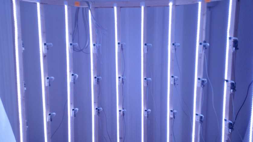
LED Strips are attached to the pillars of the body digitizer to provide 360 degrees of lighting for the subject to be scanned. The LED Strips are connected to a custom-built control board which uses signals fired by a dedicated PI that can turn LED Strips on and off. We follow the principle laid out in https://www.pi3dscan.com/index.php/instructions/item/led-lighting-control to allow for three brightness settings: Off, "50% on" and "100% on".
 LED Strips
We use daylight white colored LED Strips powered at 12V to provide all lighting. Our particular LED Strips use the SMD 5050 LED type (16-22lm per LED, [2]) at 60 LEDs per meter, but the as long as the overall brightness of the setup is about the same, other configurations of LED strips (other LED types, more or less per meter, etc.) will work, too.
The setup supports two LED strips at two meters each attached to each of the 24 pillars of the digitzer cage, though we use only one LED strip in practice as it provides sufficient brigthness for now. Using the control board (described below), one half of these (or both) on all pillars can be deactivated to provide 0%, 50% or 100% of the total brightness.
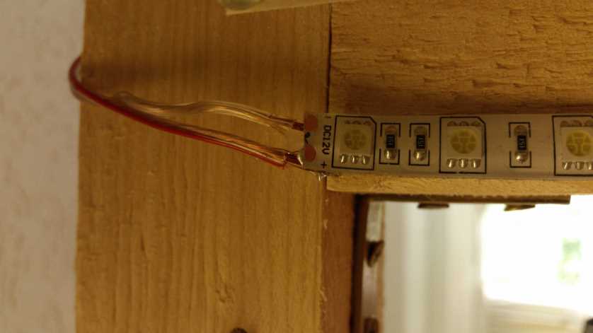
One LED Strip is two meters long and attached to the pillars using glue. We have one control board for 4 LED strips each, where the LED strip power wires are connected to it using terminal screws.
In order to physically reach those boards, we soldered about 1.3m long speaker cables to the ends of the LED strips which transfer power from the board to the LED Strips. Speaker cables are used because they are cheap and can carry high currents without overheating, more than enough for the LED strips we used.
 Control board
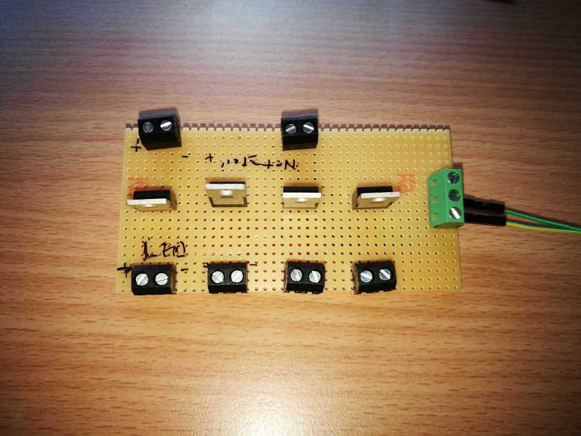
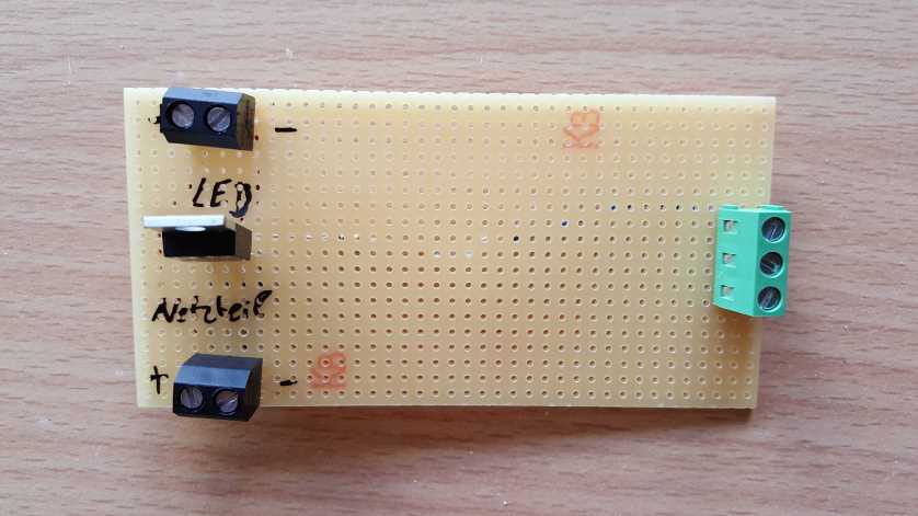
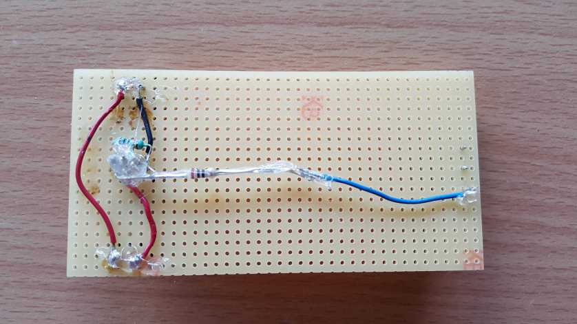
We use a custom-soldered control board using MOSFETs to turn LEDs on and off. One raspberry PI (and the LED client running on it) drives two dedicated signals out of its GPIO pins (at 3.3V), one for each half of all of the LED strips inside the body digitizer. Small wires connect to the green terminal screws dedicated to the PI signals (seen in the image above), which are connected to the GATE pins of the transistors, activating them when the PI turns the pin on at 3.3V.
We use left-over LAN wires to carry the the PI signals from board to board, all around the cage (so only one PI is needed to switch all the LED strips on and off).
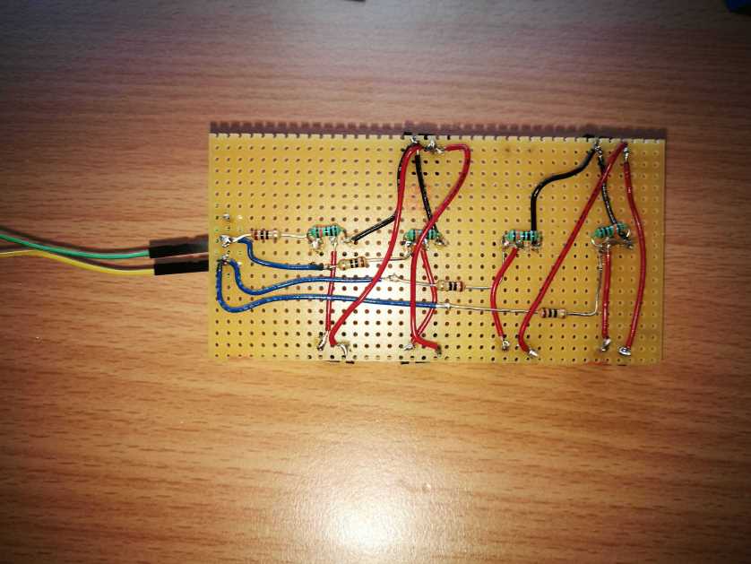
Each board uses 6 two-pin terminal screws, one 3-pin terminal screw, 4 MOSFETs of type IRLB8721 (one for each LED strip), 4 resistors at 10 ohm (between the PI signal and GATE pins of the MOSFETS) and 4 resistors at 10k ohm (between GATE and SOURCE pins of the MOSFETS, to make the LED strips switch faster).
Problems and improvements
The ordered LED Strips came in lengths of 5 meters and could be cut (using basic scissors) at certain length intervals marked on the LEDs. However for total strip lengths of 2 meters, cutting up a 5 meter roll results in a left over one meter long LED strip. Fortunately these leftovers can just be soldered together at exposed copper areas.
Initially the LED Strips were attached to the pillars just via the built-in glue on their back, but the warm temperature of LEDs after long operation slowly detached the glue over time.
If you aim for less radiometric "tainting" of the captured colors, using neutral white color temperature for the LED might be an improvement (we haven't tried). We used daylight white because they were the cheapest LED strips we could find, and partially because we underestimated the blue tinge they provide. It should be noted that in the finished 3D scan the blue tinge is barely noticeable.
The LED control board can be extended to allow for detailled control of each single LED strip. Since the board already has one MOSFET for each LED strip, all you would need for this is one dedicated signal (coming from a PI) for each LED, or design some kind of binary addressing scheme (to reduce the amount of required signalling wires).
Software
Please note that the software is open source and can be found at https://github.com/Heishe/pi3dscancontrolapp
This section will not go into technical details of the programming aspects of the software. Please refer to the actual repository for the project for that.
Workflow
The custom control software only takes care of starting the image-taking process and storing all the received images in a local directory. Currently, these have to be manually imported into photogrammetry software of your choosing. We use Agisoft Photoscan.
From the user-perspective, there's a single terminal program that takes care of making images and controlling the LEDs. The NodeJS-based application is started in the console or from a terminal and asks the user for input.
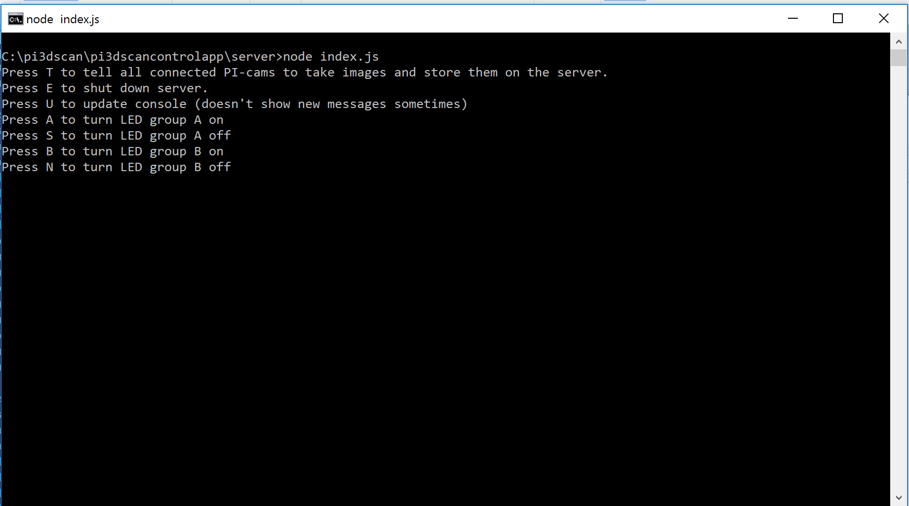
The user can turn LEDs on and off, or tell all PIs to take images of whatever is currently inside the body digitizer. Received images will be stored in a local directory ( ./images by default) that is named according to the time that the images were taken. The images themselves are just named in order of their arrival at the server.
By default the software will take two sets of images right after the other. One with the projectors disabled (showing a black screen), and one with the projectors showing a pattern and "drawing" it on top of the person in the scanner in order to enable the photogrammetry algorithms to better work with relatively featureless surfaces.
Software architecture setup
The software is based on NodeJS, a runtime environment that enables execution of Javascript (which usually runs in a browser) code in native environments, and exposes typical native functionality (such as file operations) to Javascript code.
The software is split into a server application, and separate client applications that fill different purposes. There's a default "client" that takes care of taking images on the actual PI client, a "beamer client" that takes care of controlling one projectors connected to the respective PI, and a "LED-client" that takes care of controlling the signals used for turning LED strips off and on.
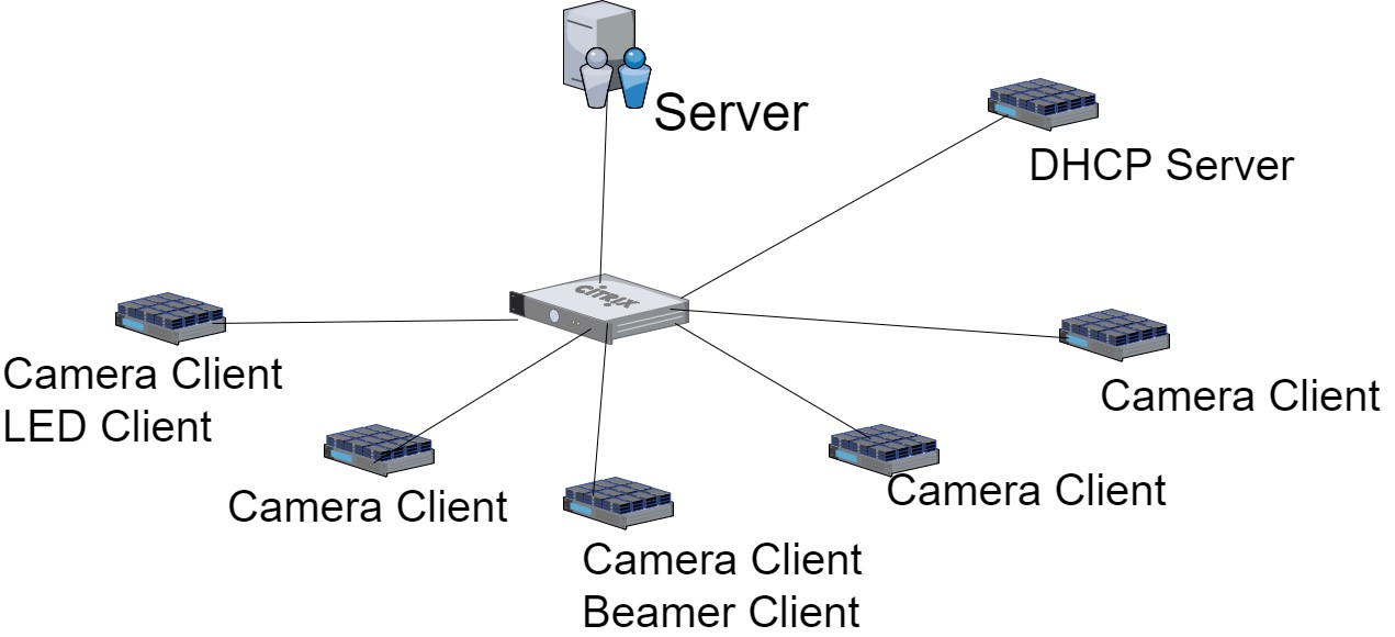
All the clients connect to a specific server IP, and handle automatic connection and reconnection (in case connection is lost). Whenever the user of the server application gives a specific command, the server sends the relevant commands to all connected clients of each client type. This enables easy "plug&play"-like behavior of the PIs. If you need, for example, an additional projector, you can just connect an extra PI with the correct software installed and it will communicate with the server automatically.
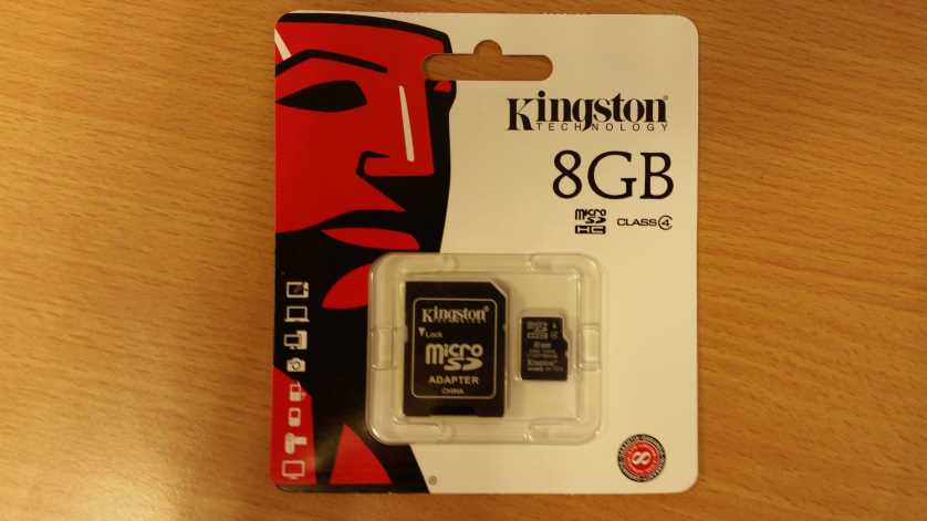
PI configuration
We configured a single "master"-SD card and copied its image onto all other SD cards for the 100 client PIs using Win32DiskImager
[1].
The default clients for taking images are pre-installed on all images. LED-Clients (which only one PI executes) and projector clients were configured manually after all SD cards had already been set up. This is because we previously did not know which of the PIs should execute which of the extra clients.
We use the PM2 NodeJS process management tool to keep clients running in case of errors, and also to automatically start the clients when the PI boots up. This way, adding a new PI effectively means cloning another SD card and then just connecting it to a power source and the network, after which the PI should work automatically.
A single, separate, PI serves as a DHCP server and "LED-Client" for controlling LED-Strips. The Raspberry PIs taking images therefor do not have static IP addresses assigned, and instead procure them from the DHCP server.
Updating PI software
We use pssh (parallel-ssh)
[2] and pscp (parallel-scp)
[3] to update software on all running clients at once. These enable execution of SSH-based commands on an arbitrary number of connected machines in parallel, and prevents having to update each individual PI one-by-one.
Problems and possible improvements
During development some PIs frequently disconnected and reconnected in spurious intervals. This is when we noticed that some PIs had power supply issues which we had to solve (refer to the power supply section for closer examination).
The process of taking images and importing them into photogrammetry software can be automated if the software of your choice offers some kind of programmable API.
Projectors for homogeneous surfaces
Photogrammetry algorithms have problems dealing with unchanging surfaces where no or few apparent surface features are visible. For example, single colored shirts, suits or surfaces with surface patterns that are too small to be visible in photos of the used resolution can show up as holes in the final 3D scan.
To aid algorithms, it is possible to project an image pattern onto the subject inside the digitizer which breaks up the uniformity and makes it easier to recognize the shape of the object. In the final workflow, two sets of images can be taken a few dozens to hundreds of milliseconds apart, where one set will contain images with the pattern projected, and the other contains no projected patterns. Then, the 3D mesh can be reconstructed using data from the patterned images while the ordinary photos can be used only for generation of the model's texture.
Hardware:
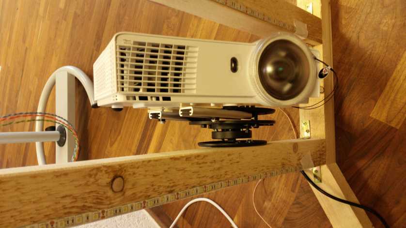
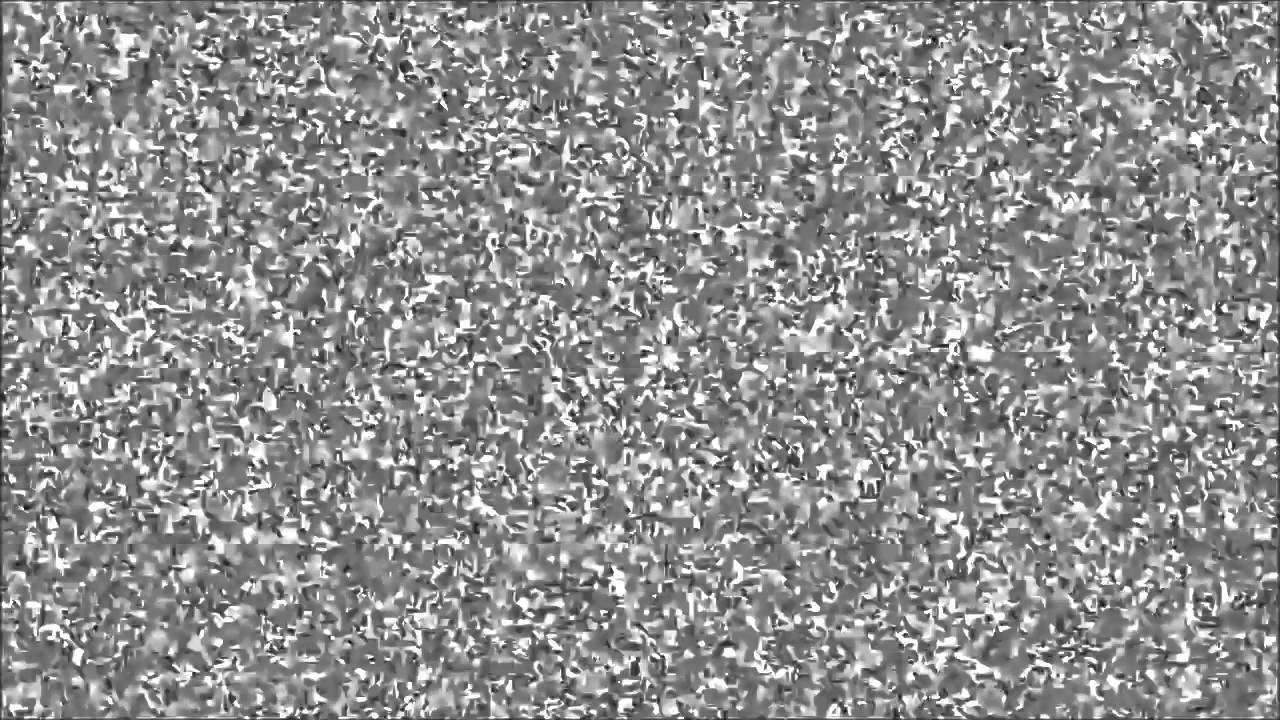
In practice, the pattern can be a simple noise texture and therefor, the used projectors don't have to be high resolution. We use four Optoma GT 760 short throw projectors set up around the cage. The projected images are set up to hit the subject evenly from all sides using basic visual inspection. Each of the projectors are connected to a single Pi (via HDMI), which take care of controlling the projected pattern.
Software:
To control the LEDs, we use a separate client application based on the same boilerplate code as the camera and LED NodeJS clients.
We use a Raspberry Pi port
[1] of NW.JS (previously 'node webkit') framework to open a window and display a fullscreen image of the chosen pattern.
Like other clients, the application automatically connects to the server on start, and the server software sends commands for turning the pattern ON and OFF whenever required. When no pattern is supposed to be visible, the application does not turn off the projector output which would take too long. Instead a basic black image is drawn, as black pixels result in the projector not actually projecting anything.
3D Model
Below, you can view Philipp Gagel's digitized body model. The model is about 30MB large so loading may take a while (screen will remain black until then):
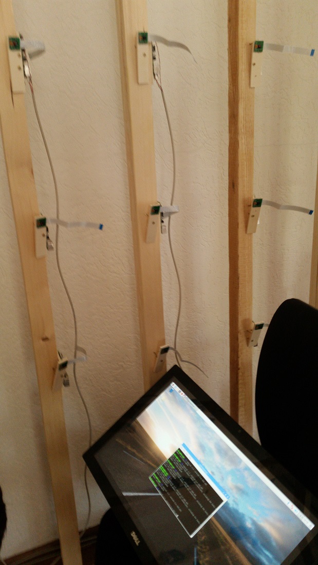
Final Setup
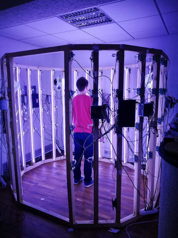
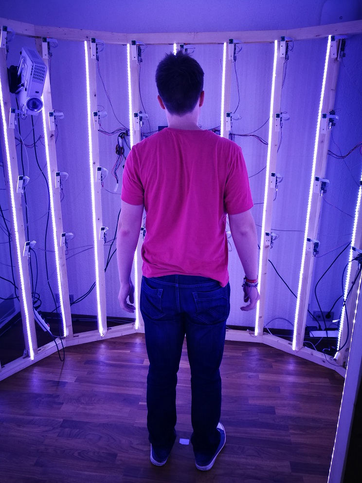
The images above show what the final scanner looks like in the process of taking images.
Built by Travis Gesslein and Daniel Scherer,
with friendly support by 

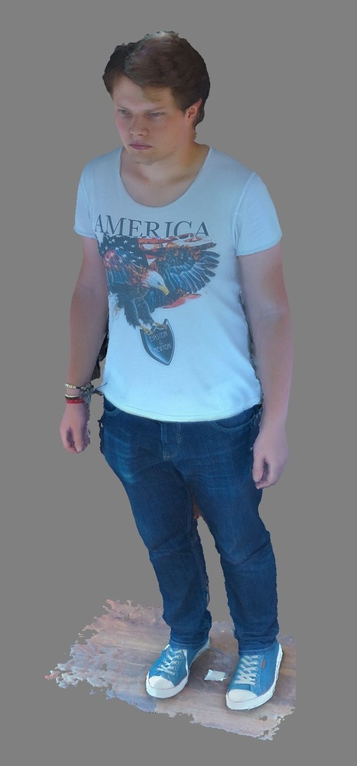
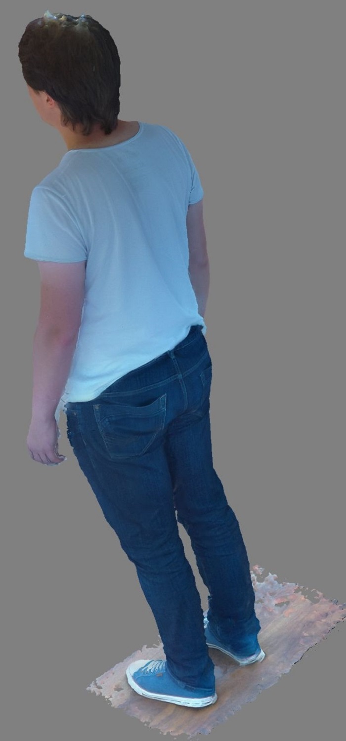
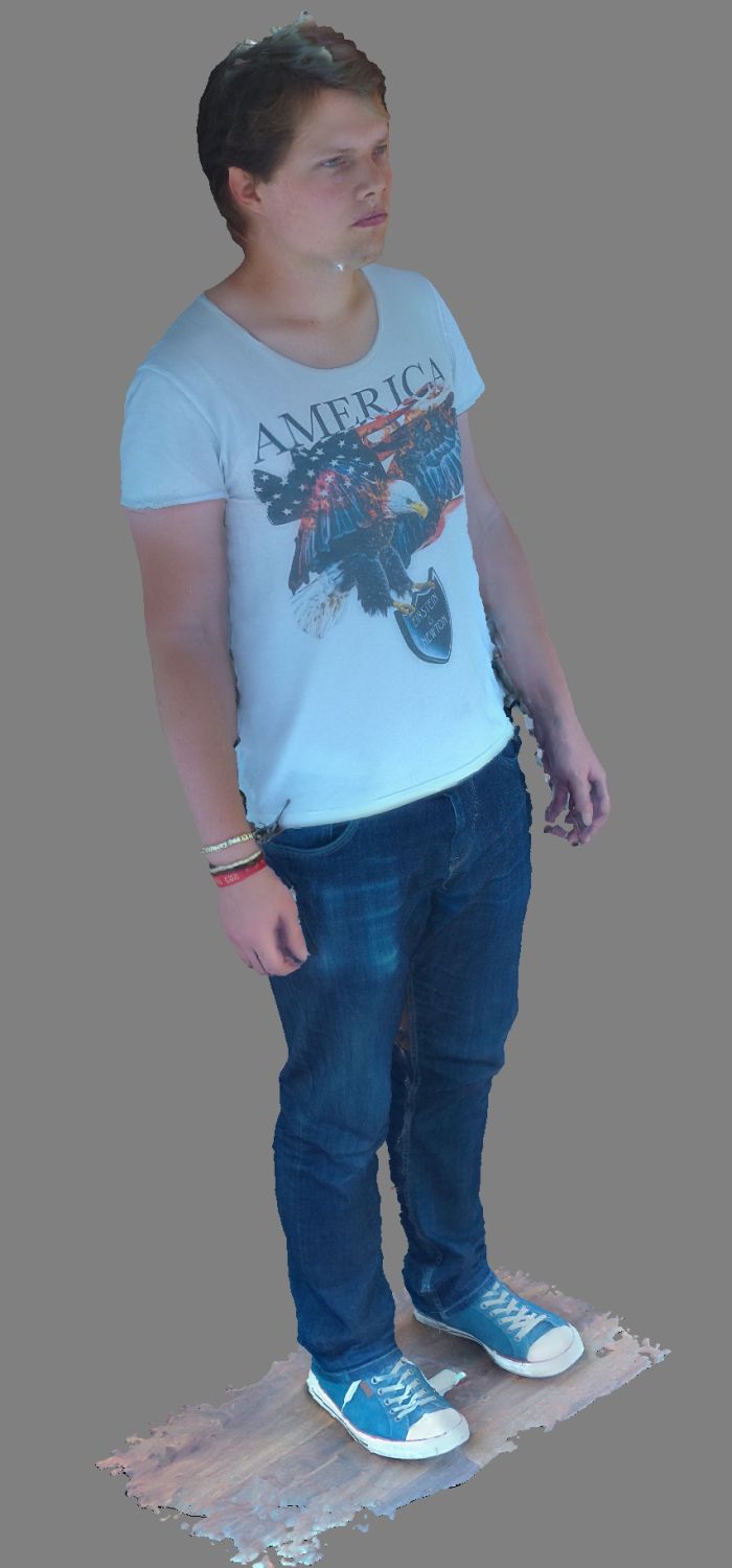
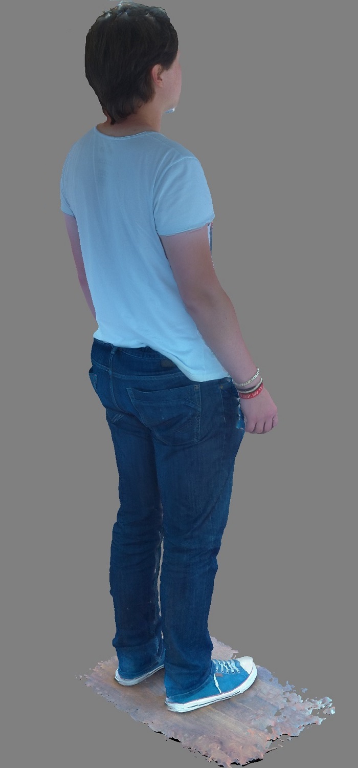
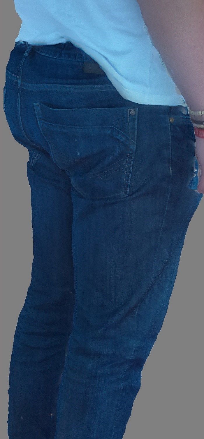 Shown above are images of an example scan of volunteer Philip Gagel. Note artifacts on the top of the head and below the chin, resulting from lack of cameras in our setup that directly image those areas.